A blast plan (blast design sheet) in Crosscut takes five steps: lay out the block and its hole pattern, charge the holes by rules, wire the delay network, check the fly-rock danger zones and look over each row in section before printing.
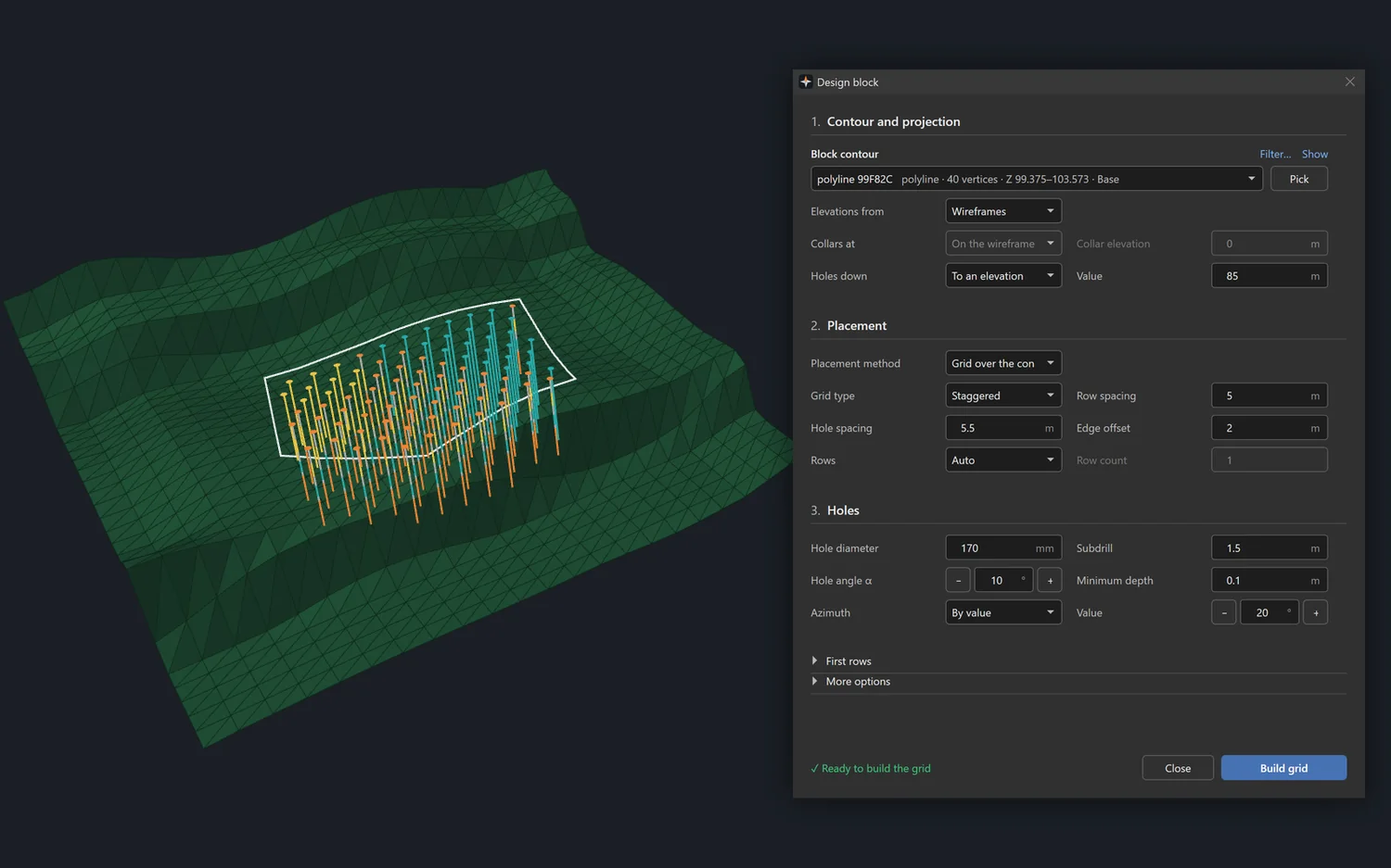
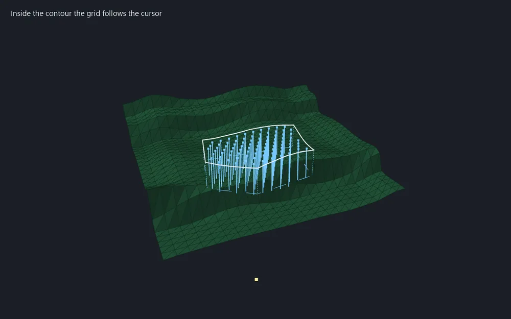
Describe the block, then show in the 3D view where the grid starts and where its rows go. The layout is drawn on the model before any hole is created.
Result: one blast block with all its holes.
Read more in the guide →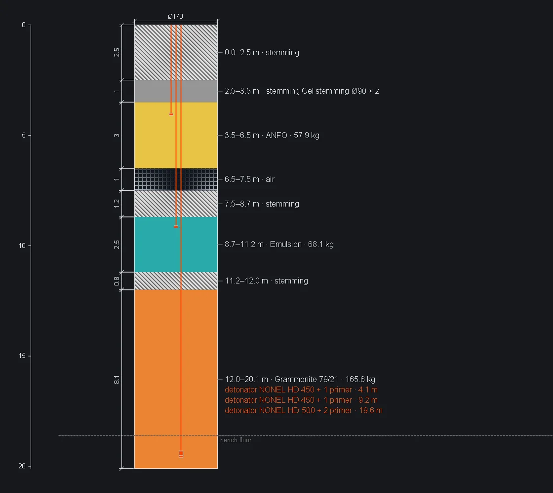
A charge template says what a charge is made of. A rule says which holes get it, by conditions on the holes’ own fields.
Result: the charges go into the holes only after you have checked them in the table.
Read more in the guide →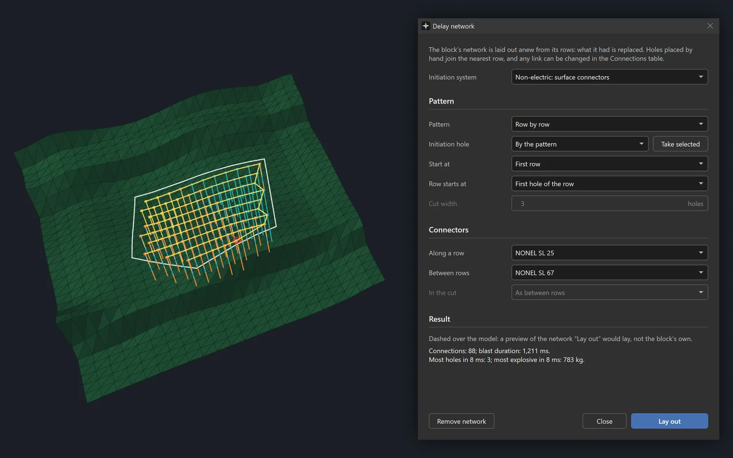
Which hole fires after which. Non-electric, with surface connectors between the holes (row by row, diagonal or cut), or electronic, with each detonator programmed to its own delay.
Result: a firing time for every hole; the summary gives the blast’s duration and the largest mass in 8 ms.
Read more in the guide →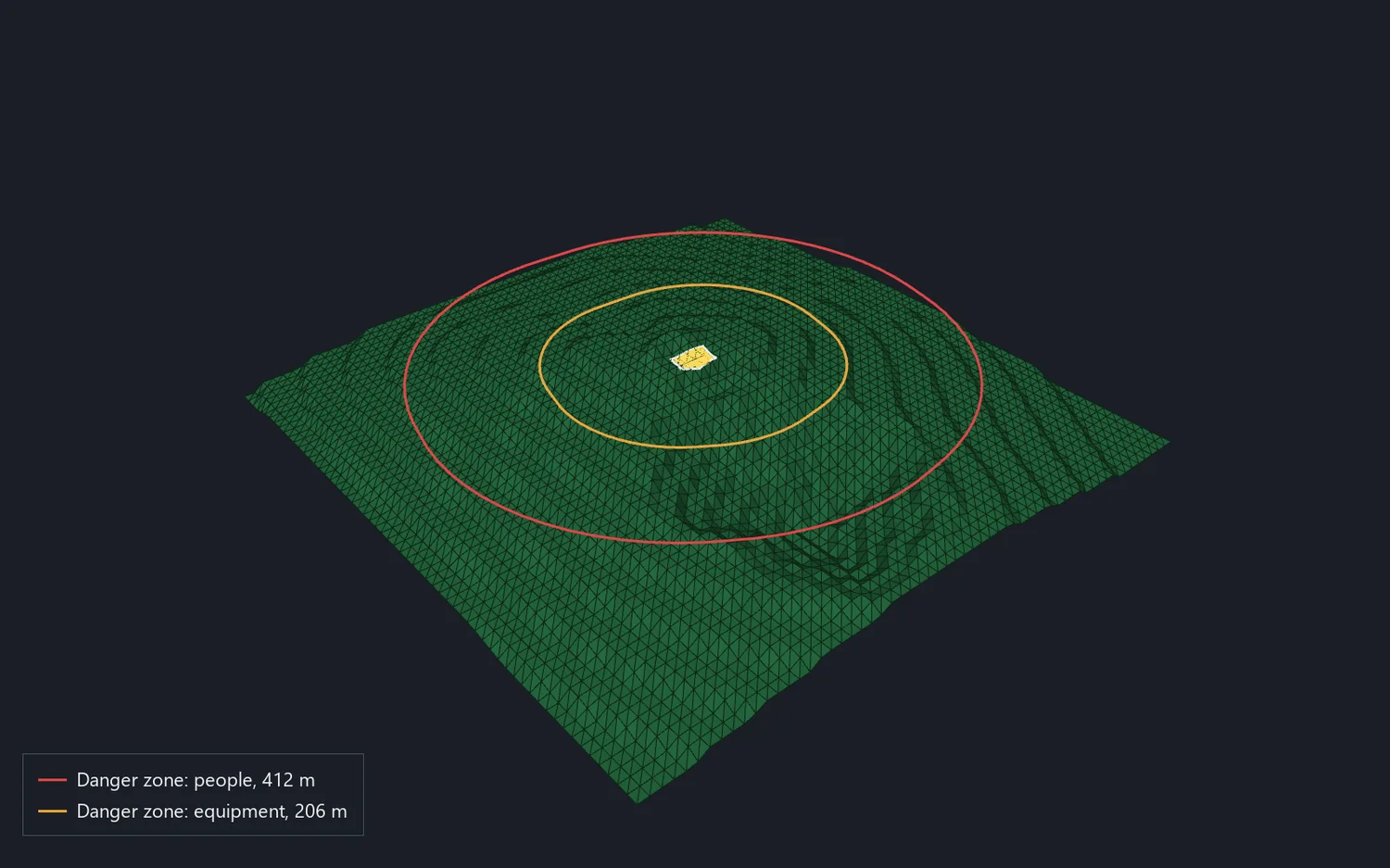
Two danger zones, for people and for machines, by one of three methods: McKenzie (ISEE), the CIS safety rules or Lundborg. The zones are drawn over the model while the form is open.
Result: the danger distances; nothing enters the project until you build the zones.
Read more in the guide →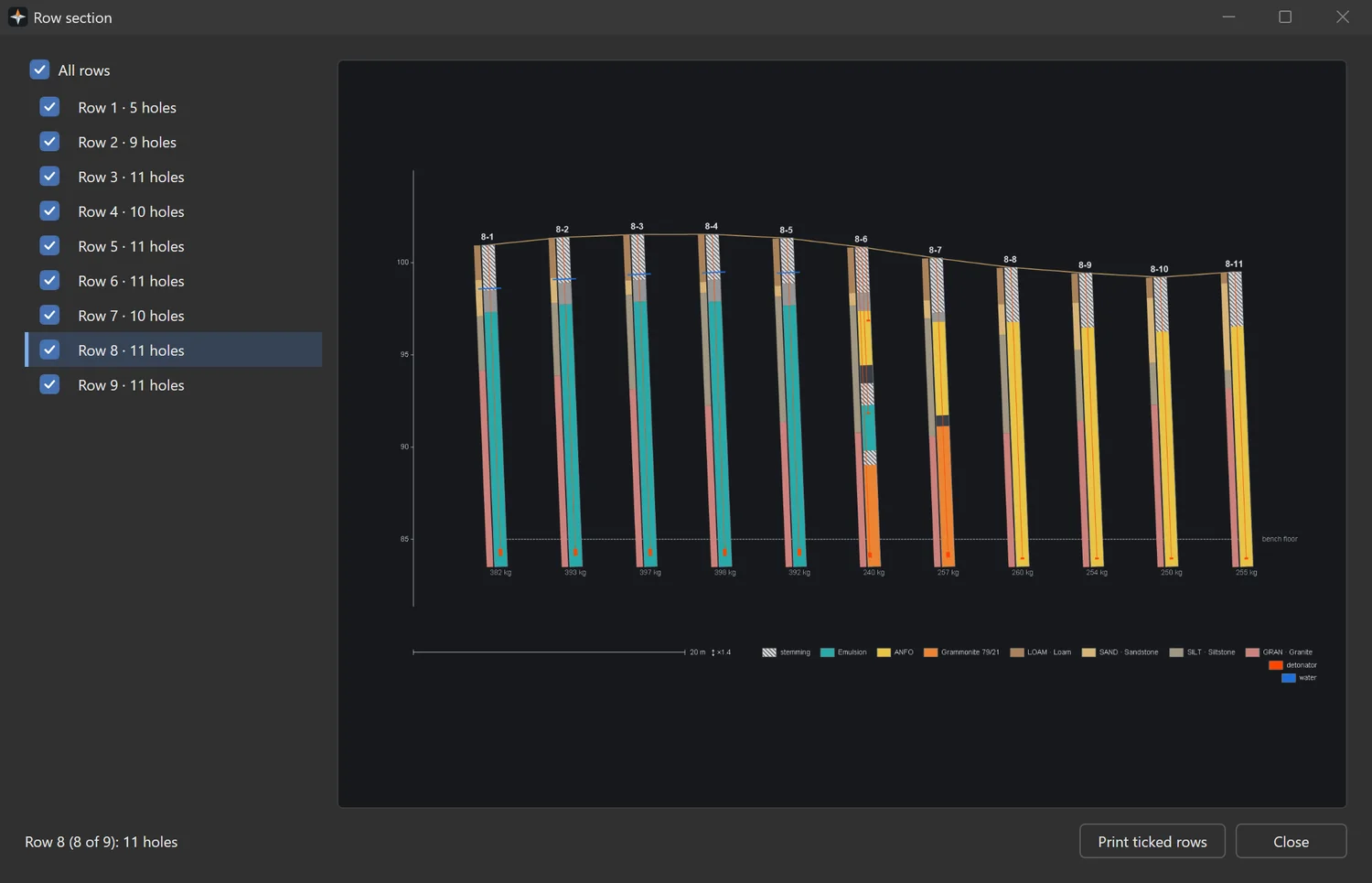
Shows every row of the block side by side at true elevations: each hole with its geology and its charge, water and the bench floor. The rock and the charge can be compared hole by hole.
Result: a section of each row with charge and geology, and a landscape sheet for each ticked row.
Read more in the guide →The demo is the full program: all six sections, nothing switched off. Windows 10 or 11, 64-bit.